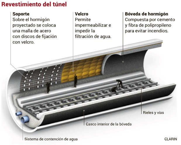
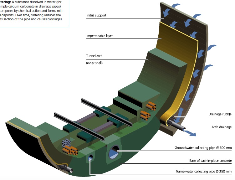
Impermeabilización y conducción de aguas en el túnel
Impermeabilización con velcro
Conducción de aguas en el túnel a través de tuberías situadas en la parte inferior de cada tubo, debajo de las vías
Ver en planos, sección sostenimiento de impermeabilización de los tubos
METODO DE EXCAVACIÓN
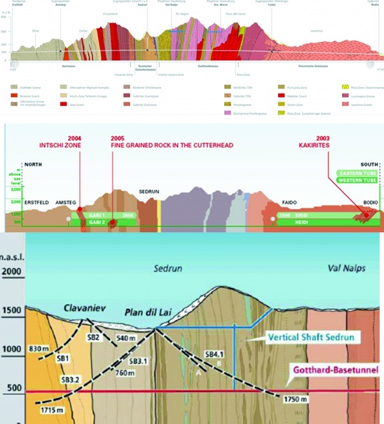
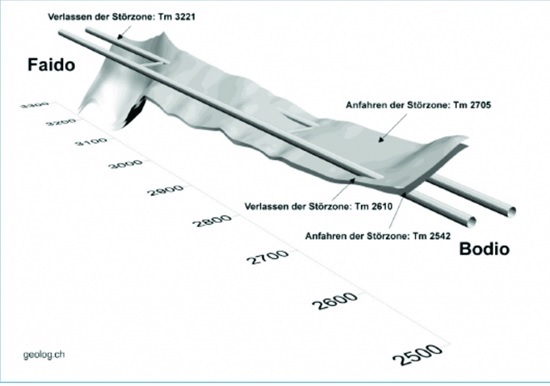
PERFILES GEOLÓGICOS
TBM tipo
TBM open hard-rock gripper
longitud (km)
97
Convencional
longitud (km)
54
Roca excavada reutilizada (kt)
Rellenos
Estéril de hormigón
5800000
Escombreras
18200000
Otros
SEGURIDAD EN OPERACIÓN ( Reglamento(UE) 1303/2014 que hace de obligado cumplimiento la TSI-SRT)
INSTALACIONES DE EVACUACION
Salidas de emergencia a la superficie laterales y/o verticales cada
15-20 km
Galerias de conexión transversales entre tubos independientes cada
Control de humos: diseño de la zona segura y su equipamiento para proteger a las personas que utilicen las instalaciones de auto-evacuación
ESQUEMA
Descripción
The Fire/life safety system:
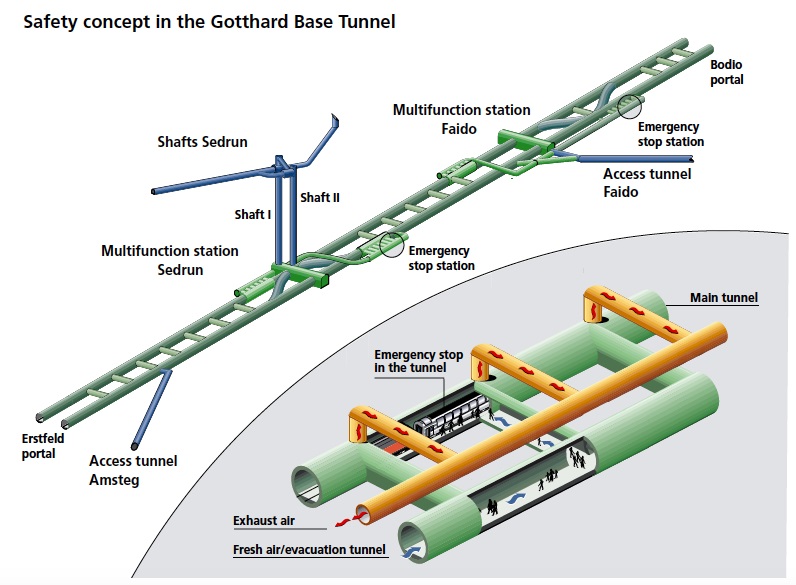
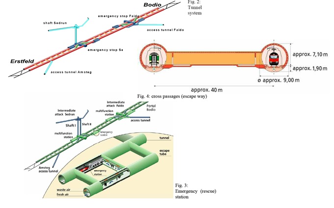
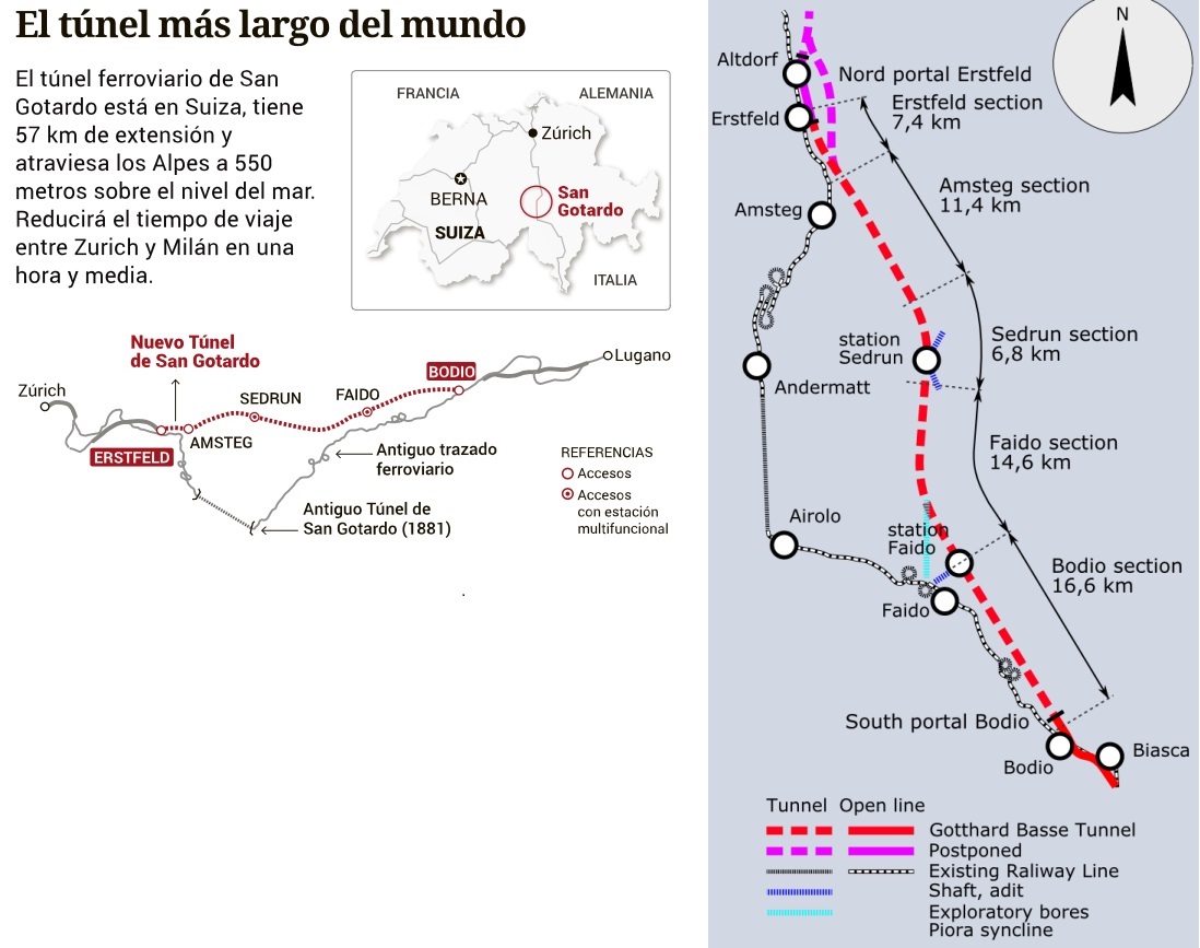
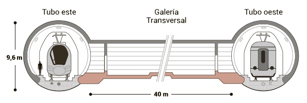
The tunnel system (see Fig. 2) mainly consists of two single track tunnels with two train-crossover sections in the so called multifunctional stations. Along the tunnel, cross passages are located every 310?325 m approximately; the horizontal distance between the tube axes is varying between 40 and70 m. In front of the tunnel portals turn-out tracks are arranged.
For tunnel safety planning, in first priority preventive measures have been designated and in second priority curative measures have been defined in addition. This principle paid off during decades in railway technique. Should an incident happen in spite of these measures, particular measures facilitating the self- and external rescue will be applied.
In general every failure of the safety system has to be prevented, otherwise the personnel on the spot (train crew, engine driver) has to deal with it (radio contact to the control centre). If unsuccessful, the train has to leave the tunnel or stop at an emergency stop station with highest priority. Assistance from the outside can be expected depending on the exact position of the train in the tunnel after 30 minutes at the earliest (e.g. train at emergency stop station).
In the tunnel control centre well-trained Traffic-Controllers survey the train running and the technical infrastructure. The Swiss Federal railways develop an early warning system to detect irregularities in the operation in real time. In case of an incident the Traffic-Controllers activate defined and rehearsed procedures using check lists. Always the purpose is to manage the situation quickly, preventing an escalation.
It is also important to ensure the operating flow and to achieve a stable operating situation.
In case of a fire on board of a (passenger) train, the procedure of the safety concept depends on the positionof the train in the tunnel. Three cases have to be taken into account:
1. The train is running in the last section of the tunnel (after the second multifunctional station): the train has to reach the portal and will stop in the open air. Passengers are able to leave the train.
2. The train is running in the first or in a intermediate section of the tunnel: the train has to reach the next multifunctional station and stops there for the evacuation of passengers (see Fig. 3). The passengers reach the sheltered area of the emergency stop station within 3 to 5 minutes. Prior to the arrival of the train, after the fire-alarm, the lights of the emergency station will be turned on, the sliding-doors of the escape ways will be automatically opened and the ventilation system starts the extraction of smoky exhaust air from the traffic tube trough the middle of the seven fire dampers (only after exact location of the fire it will be possible to open the nearest fire damper).
After evacuation from the train without using stairways or elevators passengers will wait at
the emergency stop station of the opposite tube for a rescue exclusively by train(multifunctional
station Sedrun: no evacuation through the shafts; multifunctional station Faido: no evacuation
through the access tunnel).
Fig. 3:Emergency (rescue) station
The emergency stop stations (sheltered areas) as well as the lateral and connecting galleries are
furnished with fresh air independent of the traffic tunnel system, they are kept smoke-free
through overpressure. An evacuation train conducts the passengers outside the tunnel. And this
leads to another principle: the rescue from the outside is rail-bound. The evacuation train is either a train emptied in front of the tunnel or a train already in the tunnel.
Fire-fighting and rescue trains come in action from the south-end as well as from the north-end of the tunnel. The rail-bound rescue is proven and trained for years at the Swiss Federal Railways
(Simplon Tunnel 19 km, Gotthard Tunnel 15 km). In order to shorten the time period until the
forces are ready, a close co-operati
ESQUEMA BÁSICO DE LOS SISTEMAS Y MEDIOS MECÁNICOS para conseguir el control de humos para las personas que utilicen las instalaciones de auto-evacuación tanto en las zonas seguras como en los puntos de lucha contra el fuego
ESQUEMAS
Descripción
https://www.youtube.com/watch?v=aL8PjaDPxHw The Ventilation system:
In February 2002 the Swiss Federal Office of Transportation requested to upgrade the ventilation system of the Gotthard Base Tunnel to permit the extraction of smoke at 7 different locations in both underground emergency stations, in order to ensure sufficient air quality, temperature and visibility conditions in case of a fire break-out and the necessary evacuation of passengers and staff.
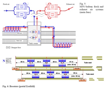
In the system of the Gotthard Base Tunnel, emergency stations are located in themultifunctional stations,where burning trains will stop in case of fire. To permit an efficient and safe evacuation of the passengers, it is required to extract exhausted air (smoke) near to the fire and to supply fresh air with overpressure in the escape ways and in the opposite tube (see Fig. 5). Main fans (redundant, 4x1,5 MW for extraction and 4x 2,4 MW for fresh air) will be installed in the ventilation plant located near the portal of the intermediate access of Faido as well as in the ventilation plant in the cavern on shaft top in Sedrun. The amount of air blown in and exhausted will be about 200 m3/s and 250 m3/s respectively.
In each emergency station seven fire dampers, located on the top of the lining, and six emergency sliding doors will complete the ventilation system.
El sistema de evacuación de humos y los medios mecánicos de ventilación fueron expuestos en apartados anteriores .Para más información ver THE GOTTHARD BASE TUNNEL FIRE / LIFE SAFETY SYSTEM by Davide Fabbri, Chief designer Engineering joint-venture Gotthard Base Tunnel South. The technical rooms are separated from the railway tunnels: in case of fire, as normally during service,these rooms will be ventilated to maintain the required temperature. Overpressure in case of an accident will prevent the propagation of smoke and air with high temperature in the technical rooms (seeFig. 5).
MFS Sedrun: fresh and exhaust air systems (main fans) Subsidiary boosters (6 jet fans, each rated at 40 kW) will be additionally installed near to both tunnel portals in Bodio and in Erstfeld as measure to maintain the difference of pressure between the tubes(see Fig. 6). This is very important, if a burning train will stop close to the portal.80 m
PROYECTO TÉCNICO MÁS DETALLADO DEL SISTEMA DE CONDUCCIÓN DE LOS HUMOS EN CASO DE INCENDIOS EN TRENES DE PASAJEROS
ESQUEMA BASICO
Nº de ventiladores en galerias de acceso
Nº de ventiladores en los tubos
Sistema SOCARDO
CARACTERISTICAS DE LOS VENTILADORES
Estación
Nº Ventiladores
Potencia (Kw.)
Caudal (m3/s)
Modo
estacion de rescate Faido
4
4x2.400
320
SOPLANTE
estacion de rescate Sedrun
4
4x2.400
320
SOPLANTE
estacion de rescate Sedrun
4
4x1.500
250
SOPLANTE/ASPIRANTE
estacion de rescate Faido
4
4x1.500
250
SOPLANTE/ASPIRANTE
DESCRIPCIÓN BÁSICA DEL PROYECTO DE EVACUACIÓN DE HUMOS
Ver revista Obras urbanas, nº57 El túnel base de San Gotardo: Los pozos de Sedrun, Superestructura y Conclusiones (6 de 6) https://www.obrasurbanas.es/san-gotardo-sedrun-conclusiones/
PROYECTO TÉCNICO MÁS DETALLADO DEL SISTEMA DE CONDUCCIÓN DE LOS HUMOS EN CASO DE INCENDIOS EN TRENES DE MERCANCIAS
INSTALACIONES DE LUCHA CONTRA INCENDIOS
DESCRIPCION BASICA DEL PROYECTO
ESQUEMA
FFFS (Fixed Fire Fighting Systems)
SI
AFFF (Aqueus Fil Forming Foam)
SI
CAFS (Compressed Air Foam Systems)
NO
Inertización
Water Mixt System.La Oficina Federal de transportes de Suiza ha dispuesto varios trenes de rescate LRZs en puntos estratégicos de los principales corredores alpinos.Las empresas Windhoff Bahn-Anlagentechnik and Dräger Safety deberán entregar en 2018 trenes de lucha contra el fuego y de rescate que cubrirán tres de las líneas principales. Para la extinción se prevé un tanque de 50.000 litros de agua y 1.800 litros de espumante. Los vagones de rescate pueden evacuar 60 personas que dispondrán de equipos de respiración autónoma.Los trenes de rescate LRZs están previstos para pasajeros y no parecen diseñados para luchar contra un gran incendio de mercancías.