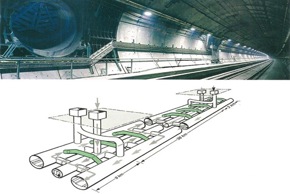
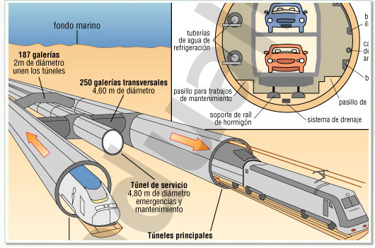
Tunel submarino internacional más largo / Una galeria central
EUROTUNNEL
--------------------------------------
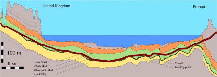
Desde Francia (Calais, Pas de Calais) hasta Gran Bretaña (Folkestone, Kent)
50 Km.
Tunel submarino internacional más largo / Una galeria central